Continue to Site

Welcome to EDAboard.com

Welcome to our site! EDAboard.com is an international Electronics Discussion Forum focused on EDA software, circuits, schematics, books, theory, papers, asic, pld, 8051, DSP, Network, RF, Analog Design, PCB, Service Manuals... and a whole lot more! To participate you need to register. Registration is free. Click here to register now.

Rectena conversion efficiency

Tinoonga

Newbie
Joined
Jan 3, 2024
Messages
4
Helped
0
Reputation
0
Reaction score
0
Trophy points
1
Activity points
31
Hi
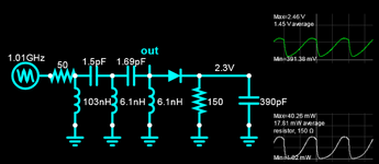
I am trying to simulate a chart with conversion efficiency of a rectenna but so far the info i have been reading online is for circuits which don't match with what I am working with.
What formula for conversion efficiency can i use on the following schematic. Please help
1-s2.0-S2665917422001660-gr14.jpg
 
What conversion efficiency do you want? Use matched impedances after filter transform.
Define BW , Q and 0.9 GHz expected input range. Diode impedance is dynamic, so where do you need maximum efficiency? -30 dBm? 0 dBm? or a wide range?
That won't cut it.

Do you want max conversion voltage for e-field or MPT for power or best sensitivity?
 
Last edited:
I want to reproduce the following chart

1-s2.0-S2665917422001660-gr15.jpg


The efficiency equation provided by the paper I am studying is ƞ = ((Vdc)^2/Pin RL)x100%
Where: VDC is the DC voltage that is measured at the load; Pin is the input power; & RL is the load resistance used in the rectifier
 
Where are your assumptions list? Antenna impedance s-parms, diode s-parms.
Do you know that the assumption in MPT is matched conjugate impedance?

What do you need to learn in order to do this? (search GPT)

What is the antenna impedance, BW etc?

Pls cite reference to plot
 
Last edited:
Efficiency is output (TERMG2) divided by input (PORT1) power. What's your problem to measure it?
 
I am getting stuck where i have to write an equation to use in the chart for simulation
I tried writing it as eff = p_probe2.p/dBmtow(Pin) but the equation returned an error, probably because the software didnt list dbmtow(Pin) as a variable
then i tried to just omit the dBmtow operation from the equation and wrote it as eff = p_probe2.p/Pin but it still returned an error
Writing a valid equation for the simulation is where i am stuck at
 
1704484185049.png


your filter is suboptimal for 900 MHz.
Where are your assumptions list? Antenna impedance s-parms, diode s-parms.
Do you know that the assumption in MPT is matched conjugate impedance?

What do you need to learn in order to do this? (search GPT)

What is the antenna impedance, BW etc?

Pls cite reference to plot
You did not answer my questions. I do not see anything useful in that plot.

Efficiency is simply the lowest current loss which rises with lower output power. You might as well just use a 10Mohm DMM

But for energy harvesting, MPT matches the impedance after the diode which raises the 50 Ohms but when only half-wave means half the current and thus twice the impedance for MPT. or maximum power transferred which naturally reduces the applied voltage to zero with almost a short circuit if the filter was designed for 50 Ohms. So maximum usable power demands you define the Vmin output. So if you applied 5Vp and needed 3.3V or 1.8V the load impedance will vary. But when you raise the load impedance to a filter rated for 50 Ohms each pole begins to peak and they are typically on either side of your BPF center fo or peaking high Q LPF fo then the valleys between each peak cause lower gain at fo. This is why I asked. You filter is not optimized for 900 MHz and in fact peaks > 1GHz. I have no idea what your filter specs were.

if you were wanting to harvest energy, Then you might design a narrow band BPF at 100 Ohms using a Gaussian filter to span your signal BW. I chose 70 MHz
now simulating your filter in the time domain with a low capacitance Si power diode sweeping from 910 to 1100 MHz you can see the peak voltage is 50% or 2.5V with 5Vp using a sawtooth log sweep shows a quasi-sine output

1704575410130.png

With a simpler filter now my filter below for 900 MHz.
Here log sawtooth sweep 850 to 950 MHz Rectifier Cap ESR included is irrelevant. 0.09 pF would be two striplines parallel for low pF. Inductance is approx 0.8 to 1nH/mm in stripline. The other elements could be lumped discrete parts. 150 Ohms seems to match with a little more than 50% of the input voltage. So this seems to be close to what you want.

1704574740544.png


1704575666092.png

--- Updated ---

Rev B might be a 2nd order simple LC BPF at 150 Ohms. The only difference is I used an ideal generator and lossy 50 Ohm source rather than a 50 or whatever ohm antenna.
1704578724476.png

--- Updated ---

Rev C

I would choose a high Q 4th order BPF with a suitable RF Schottky diode around 0.9pF then with no path loss and high Q get 24Vdc out with 5Vpk RF in 900 MHz using a load or a V gain of ~5 after rectification. Power transfer efficiency is 100% because I used a lossless source but only %50 of peak RF power because it is half wave rectified. I hope that makes sense. Top right plot shows generator peak power as "negative" 5.79 W and red DC out power into 220 Ohms as 2.65 W almost 50%.
1704582626598.png


sim link http://tinyurl.com/2ymhmc9t
 

Attachments

  • 1704575014909.png
    1704575014909.png
    57.6 KB · Views: 7
Last edited:

LaTeX Commands Quick-Menu:

Part and Inventory Search

Welcome to EDABoard.com

Sponsor

Back
Top