Continue to Site

Welcome to EDAboard.com

Welcome to our site! EDAboard.com is an international Electronics Discussion Forum focused on EDA software, circuits, schematics, books, theory, papers, asic, pld, 8051, DSP, Network, RF, Analog Design, PCB, Service Manuals... and a whole lot more! To participate you need to register. Registration is free. Click here to register now.

driver compression logic

yefj

Advanced Member level 3
Joined
Sep 12, 2019
Messages
996
Helped
1
Reputation
2
Reaction score
3
Trophy points
18
Activity points
5,845
Hello, I have the following circuit where the heart is the BJT.when i put the resistor to be 50Ohms i get a good sine current on the inductor L1 shown below.
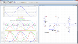
But when i put 25 ohms i get compression .
In the compressed version i see that the current going threw the inductor is much higher and it seems like for input voltage of 3.8V the current reaches its maximum and going threw a compression.

does the current compression situation happens because the PNP NPN switch threw other states?
What is the logic of the cause the current threw L1 gets compressed?
Thanks.
1702656259139.png


1702657019308.png

1702657488455.png
 
Hello unfortunety i already manufactyred the circuit shown below.
I only need 50mA current threw the coil i was just trying to understand the limitations.

I see now that i have a big problem with the BJT beacuse they cant handle much power .
my degrees of freedom is changing the R6 R1 R4 R8 R7 resistors.

I used R4 to lower the current on the coil to 50 mA.
However as you can see bellow i get power consumption of 640mW.
1.Where can i see in the data sheet the power which it could handle?
2.in case that it cannot handle such power can i lower the power threw the BJT using R6 R5 pair?
Thanks.
1702750723226.png
1702748928042.png
 
Hello , my only spec is to put 40-50mA of current on L1 inductor so non of the components will be damaged in the process.
I am measuring the power threw PNP by Ic*Vce.
I have managed to lower the power threw the BJT to 240mW as shown bellow while keeping the current of 50mA threw the L1 coil.
Where can i see the maximal power consumption for this component in the data sheet below?
Where can i see the reccomended power consumption for the BJT on the data sheet below?
Thanks.
1702753909708.png

1702753891346.png
 
Where can i see the maximal power consumption for this component in the data sheet below?
Tony already told you: R_th_ja is the thermal resistance.
Multiply it with the power dissipation to get temperature_rise.

A simple internet search gives many hits. I´m sure ther are online calculators.
Almost every simiconductor manufacturer provides documents.

Klaus
 
I used Falstad which has the old uA741 and I got it to work with 131 mW avg for each transistor
SC-70 case transistor has an Rja = 272 'C/W thus Rj rises 272 'C/W * 0.31 W = 84 'C rise with a 68 Ohm load.
Since Power is proportional to R. you can reduce this temp rise with a load of 90 Ohms by 25%. and nothing else needs to change.

I used
R5,R7 = 180
R6,R8 = 68 = Load, R9 (182mW)
R1 = 0
Supply average power was 368 mW, , 1.12Wpk

It is important to know that a typical 1/4W resistor operates at 100'C above ambient so you show derate ~ 50% or double up on pwr rating.and similar for all devices,
if your OA is still clipping then reduce PNP Re by 10% to boost pullup.. This asymmetry is common.

SC-70 case transistor has an Rja = 272 'C/W that means the case temp is somewhere in between which you can compute by Rjc value in the datasheet.


So if I can get the 26 mA limited 741 to work, you should be able to get yours to work.
--- Updated ---

If you did not know thermal version of Ohm's Law before , you should by now and don't use 30V of supply when you only need 10Vpp for a linear power.

When you want to learn even more efficient ways, tell us the purpose and reasons for choices.
 
Last edited:
Hello Tony my Rja is 500K/W which is 226.85 C/W.
I have change my values to what you recommended as shown in the schematics below.
The circuit gives a good stable 52mA ash shown below.
Reagrding the rise in temperature, in the plot below i get to peak of 320mW=0.32W
272*0.32W=87C which is a big problem for my bjt.
Is the a way to lower even more the power consuption of the BJT?
1702811951930.png

1702813014882.png

1702813045780.png

1702813262922.png

--- Updated ---

UPDATE:
Hello i have changed the values of R6 R5 pairs as shown below.
As you can see it lowered my power consumption on the BJT while keeping the desired current on the inductor.
by your good advice i got POWER*Rja=114mW*226.85C/W=25.86 C
1.I know that in general i cannot improve one thing without getting worth other things
what could gone worse by this new configuration?
2. given rise in 25C by Arrhenius law shown bellow, what will be the life span of this bjt?
Thanks.
Arrhenius Law of chemistry predicts that all components will have a logarithmic failure rate where lifespan reduces 50% for approximately every 10'C rise in junction temperature above ambient. This has been proven and is used to compute reliability of products, separately from manufacturing defects.
1702814153669.png

1702814137997.png
 
Last edited:
Is the amplifier used for low frequency output (f < 100 Hz)? If not, you don't need to worry much about peak power dissipation, average power matters.

You can further reduce transistor power dissipation by increasing R6 and R8 to e.g. 100 ohm. Need to check actual LT1028 current limit, it has certain type variation and also temperature dependency.
 
When we talk about temperature rise or delta T,
Kelvin and Celsius are identical, since we are talking about the derivative (dT/dP).

my Rja is 500K/W which is 226.85 C/W. so 500 'K/W is an error.

'K/W='C/W

And those south of our border still talk in non-linear temperature rise 'F.
 
Hello Tony,you gave a really good avice regarding the BJT. Is there such a thing with the OPAMP?
I cant see thermal section in there.
how do i calculate the temperature rise fot this OPAMP given the attached data sheet?
Thanks.
 

Attachments

  • LT1028.PDF
    444.1 KB · Views: 22
how do i calculate the temperature rise fot this OPAMP given the attached data sheet?
Thanks.
Same way I showed you. Compute Vrms*Irms or for sine ( Vpk & Ipk) /2 or on Falstad, See Vcc power then subtract transistor power)

As a Class AB common emitter this is only 76% efficient. Minor improvements maybe but may cause crossover distortion or clipping on + side (Class B).

Using Class D or E ,like a Buck converter > 90%

1702822535326.png


Glad I could solve this problem. What's it for?
--- Updated ---

I would have suggested this way if you had +/- 6V or 0 to 12V using CMOS OA and emitter followers with 10 MHz BW to drive 10 kHz without diodes.
1702823652868.png


Now only 65 mW avg each transistor https://tinyurl.com/ylwwko5r
 
Last edited:
Hello Tony ,unfortunetly i already manufactured the circuit shown in the configuration below.

my only goal is to hve 50mA on the L1 coil.
i cannot change the BJT or OPAMP only the resistors.
Using the configuration below i lowered the power supply on the Bjt.
I know that if we improve one thing then i ruin other thing
could you please tell me if you see in this configuration some dissadvantages that could ruin my circuit in real life?
Thanks.

1702873160333.png

1702873849332.png


1702873954068.png
 
Last edited:
Hi,

Are you aware of basic OPAMP operation?
That an OPAMP regulator allways regulates that V_IN- becomes the same as V_IN+?

Are you aware, that the coil current is not DC, but AC?
If yes: what does "50mA coil current" mean? Is it 50mA amplitude, 50mA peak? 50mA peak-to-peak? 50mA RMS?

Are you aware of Ohm´s law?
If yes, then apply it on R4.

And restore all the other part values to the original values of post#1.
(for a first start)
****

You seem to randomly change part values without knowing what you do.

Example:
* In post#7 I told you that the external current gain is too low.
* in post#10 I told you how to calculate external current gain.
But in all your approaches you evene lowered ... the previously "too low" current gain. It makes no sense.

Klaus
 
Last edited:
Hello Klaus, sorry for the misunderstanding.
The input is sine wave 5V amplitude 10Khz input to the the driver i want to see a current on L1 which is a sine with 50mA amplitude.
The problem is i got the circuit below manufactured already. So i am stuck with the LT1028 and the bjt's.
my only degree of freedom is the resistors.
My only requirement is is to supply 50 mA current on L1 without any saturations as a function of Vin.
i have change my original circuit resistor to the configurations below.
The Ltspice circuit is attached.I got the desired response for L1 in the simulation.
However i am afraid i could burn the LT1028 or the BJT in the process.
As you can see belowi got 140mW RMS and 210mW on Peak Rja so POWER_RMS*Rja=0.14*226.85=31.75
Also i got 26mA current peak on my OPAMP as shown below
looking at the data sheet below could you please help me understand given this configuration if the OPAMP or BJT will function properly?
(i will try to put heat sink if necessary)
The full LTSPICE simulation file is attached.
https://www.alldatasheet.com/datasheet-pdf/pdf/16110/PHILIPS/BC807-40.html
https://www.alldatasheet.com/datasheet-pdf/pdf/70264/LINER/LT1028.html
1702883791811.png

1702883810974.png

1702883826857.png
 

Attachments

  • driver_better.rar
    813 bytes · Views: 18
The problem is i got the circuit below manufactured already. So i am stuck with the LT1028 and the bjt's.
The first approach has nothing to do with LT1028 nor with BJT.
If you want 50mAp on a 5Vp input, then there is no ther way than R4 = 5V / 50mA = 100 Ohms. Don´t ever change R4 to any other value.

I told you to keep all other values as in the original circuit. (Hopefully the schematic of post#1 shows the originall vales).
You did not follow this rule with your new schematic of post#33. Thus I won´t comment on it unless you clearly write why and show the according math.

******
You say "I got 140 mW RMS". There is nothing like "mW RMS". Sadly the audio industry confused us. They used the nonsense phrase "output power RMS" as a synonyom for "output power for minimal distorted sine". Voltage may be RMS, current may be RMS, but not power.
RMS means root-mean-square. But power is not calculated this way. Power gets simply integrated / averaged.

-> so what you mean is "140mW average power"

*****
Power dissipation.
Mind that power dissipation in a linear circuit can not be changed. This means:
(as example)
* 3V and 20mA at a resistor causes 60mW of heat
* 3V and 20mA at a diode causes the same 60mW
* 3V across CE of a BJT with 20mA collector current causes 60mW
* and so on.
This is true for every device that can not store or convert energy (capacitors, inductor, battery, motor ...)

Since your circuit is rather fixed on the 50mAp current, and 5Vp input voltage, you are fixed with R4 = 100 Ohms.
Also the supply voltage of is fixed - at least we don´t have any other information
Also your coil inductance is fixed - at least ....
Thus your overall power dissipation is rather fixed, too. The only thing you can electrically change to reduce the overall power dissipation is to reduce the bias current of the BJT stage. But this will result in higher distortion.

Also one can reduce the dissipation of power on one part .. but this automatically will increase the power dissipation of other parts.

And to reduce temperature (hot spots) you can improve heat spreading: Fan, heatsink, bigger parts, bigger PCB copper area ...

****

The biggest improvement in power dissipation will be to move to "switching circuits" instead of your linear approach.
I guess there are many audio class D amplifiers that could be used here.

****
If I´m not mistaken: the voltage across the coil is just a couple of mV. so Why use +/-15V supply? ... for sure this huge difference causes a lot fo heat.

We don´t know your options, neither your true requirements.
Indeed it took about 30 posts to find out that your main goal is to get 50mAp coil current. This says a lot.

Klaus
 
Class D operation, or SPWM. One op amp, 5V supply, single-ended. Output alternates between 5V and 0V ground. In this manner it converts one-half (upper half) of the incoming sine waveform.

It took me a while to achieve this much with a simple circuit... since it's still missing the negative portion. With enough experimentation we might find a remedy. The aim is to give the op amp a bipolar supply and make it switch between 0V and -5V during the lower half of the sinewave. Possibilities include diodes in the right place, voltage sources in the right place, level shifts, etc.

one opamp positive waveform output SPWM 5V sine signal  10kHz.png
 
Hello Klaus,Yes all of your assumptions are correct, i can only try and change the resistors.
I went back to the post 1 values under this condition i have at average 500mW on the PNP as shown below.two questions:
1.so you say not to touch anything just to put heat sinks?

2.can you please say with respect to the datasheets after what value in the OPAMP i should look in the data sheet bellow to see that i am not burning the device? there is no peak vallues to avoid in the data sheet of LT1028 datasheet.
https://www.alldatasheet.com/datasheet-pdf/pdf/16110/PHILIPS/BC807-40.html
https://www.alldatasheet.com/datasheet-pdf/pdf/70264/LINER/LT1028.html

1702897858220.png

1702898252487.png


1702898352815.png

1702898870450.png
 
This is comment #36 and you have still failed to define all your design specifications necessary to complete it.
If you had done so initially this would have been completed in a few answers.

Do you mean Io is always 10 kHz sine and always 50 mApk or 100 mApp?
What about % distortion on V or I?
Max temp rise?

What is your actual signal source? Impedance?
purpose of coil? The coil generates very little voltage and has the most distortion. why did you put Rb back in? (which spec did that help?)
etc etc

Why so much distraction about the coil current and then sense it with the wrong R value?
If you specified your source, then more would make sense, otherwise ,why use an amplifier wasting a Watt of power to generate a hundred microwatts in the coil.
1702909094800.png
 
Last edited:
1.so you say not to touch anything just to put heat sinks?
As first step.

Start with: * Original schematic / values
* 1st step: adjust only R4 to 100 Ohms. --> done
Q: Are you satisfied with the inductance current now?

R5 and R6 determine the gain and the bias. Adly they depend on each other.
Minimum OPAMP supply current is shown as 6.6mA.This value multiplied with R5 = 200 Ohms gives 1.32V
The BJT_V_BE is about 0.6V, thus leaving 0.72V for biasing.
0.72V / 25.5 Ohms (=R6) gives about 28mA (in reality it is a bit lower because of limted BJT_gain)

Let´s say we want the bias to drop to 8mA instead of 28mA

and we want to increase the external current gain to 120%,
so we need a increase the R5/R6 ratio by 1.2. Currently R5/R6 = 200/25.5 = 7.8.
--> new raito: 7.8 X 1.2 = 9.36.

The previous current gain was: 42mA collecor increase by 5.9mA LT102_supply_current increase.
The new current gain should be about 8.5
So if I like 8mA coil @ 6.6mA OA
and then the 0mA should be at 6.6mA (OA) - 8mA/8.5 = 6.6mA -0.9mA = about 5.6mA OA.
This also is when the V_BE is about 0.6V.
--> Thus R5 should be 0.6V / 5.6mA = about 110 Ohms
and with a resistor ratio of 9.36 this means R6 = 110 Ohms / 9.36 = 12 Ohms.

For sure change R7 and R8 accordingly.

Let´s see what the sim shows. (usually I use Excel for this, now I did with a piece of paper, so no guarantee)

Klaus
 
You are talking about optimizing circuit parameters. Post #33 doesn't look bad at all. What's the idea behind post #36 going back to old parameters with higher transistor power losses? Your arbitrary design modifications leave me clueless.
 
How did you "manufacture" it? Are you planning any more? or is this just a lab experiment?
What SMT case sizes?
Did you include a Cu ground plane for heat dissipation?
What is the DCR value for L1?
What is the source resistance?

I lowered your power dissipation and plotted them all together.
Each part is less than 100 mW avg. but together on some unknown assembly needs to be shown, due to cumulative effects.

1702931307070.png


Put big heatsink on the IC, and show us your "manufactured" board.
LTSpice defaults to 0.1W resistors. Your design draws > 1/4W
Same for IC. This version is slightly better.
( I think we said this design is hard to balance and even impossible unless you tell us what power ratings of parts you selected.)
When the IC does not specify, you just look up the case size on other datasheets or info sheets.
Otherwise consider 100 mW as a reasonable limit for tiny SMT parts unless you do a thermal design margin budget.

1702936103626.png
 

Attachments

  • driver_mo.better.zip
    984 bytes · Views: 17
  • 1702936030653.png
    1702936030653.png
    175.2 KB · Views: 16
Last edited:

LaTeX Commands Quick-Menu:

Part and Inventory Search

Welcome to EDABoard.com

Sponsor

Back
Top