Atal
Junior Member level 2
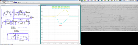
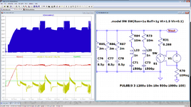
I hereby present my newly invented resonant DC-DC converter circuit, named 'Pe17 circuit'.


Features:
* Resonant half/full bridge inverter, utilizing ZVS operation.
* Constant frequency switching.
* Wide input/output voltage range operation capability, suitable also for EV battery chargers.
* Higher efficiency and power density.
Brief intro:
For more details, see US patent - US11139734:
Attached:
Presentation providing comparison between the Pe17 circuit and the LLC resonant circuit.
LTSpice simulation files for evaluation.
 S:OUT
S:OUT